Written by Edwin Prakoso
Modifying The Window Opening
Create a new Revit family. Use Metric Window.rft as the template. This window template is a rectangular window. We need to modify the opening before we continue. Move your pointer above the opening. Wait until you see the tooltip. If it says opening cut, then click your mouse to select it. If it says wall, press [tab] once to cycle between overlapping object. You should see the tooltip change to opening cut.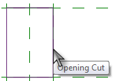
After you select the opening cut, you will see contextual tab on Revit ribbon. Click edit sketch to modify it.

In the contextual tab, draw panel, change the draw mode to center-ends arc. Click the line mid point, and its end points to create an arc. Make sure you snap it to the end points!
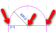
Activate modify tool. Select the horizontal line at the top most of the opening cut. Press [del] to delete it.
Creating Window Frame and Window Panel
Let us not go too detail in this section. I believe you already know how to do it. This tutorial is an exercise anyway :) We will learn a little trick to create a chain of line from existing objects as reference.Creating Window Frame
Make sure you are still in exterior elevation view. Create a solid extrusion. You will go to the sketch/drawing mode. Change the drawing mode to pick lines.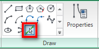
Move you pointer above the opening edge. Press [tab] until you see the whole edges highlighted. Click your mouse. Pressing [tab] will do two things: either cycle between overlapping object or select chain of lines.
Now activate offset.

Change the offset value in option bar to 50. Move your pointer above the lines you created before. Press [tab] to highlight the whole lines, then click your mouse.
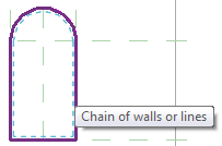
The last one: change the extrusion height to 150. You can do it in extrusion properties. Don’t forget to test your model! Try to change the width and height to see if the window frame also adjusted.
Save your Revit family.
Creating Window Panel
This is going to be your challenge: create a window panel. You can create anything you like, consider this is an exercise! We have created a simple door panel before, you can use it as reference. Or you probably want to save it for your exercise later.Creating Window Accessories
It doesn’t matter how you create the window panel. I’m not creating it, and it won’t affect our exercise later.How Detail Will You Go?
Before we create the windows’ accessories (I’m not sure I’m using the correct terminology… am I?), I will ask you a question: how many details you want to put in your family? It is not always a good practice to create everything in 3D. It can consume more computer resources, more work to do, and harder to control in parametric family. We are going to simplify this by using simple extrusion and sweep, then add pattern/model lines.So basically you need to consider two things when creating family:
- Do you want this family has different types (i.e. sizes) or only this form and size? This is related to whether you need to use parameters or not. If you only need it in one size, don’t bother to create tons of parameters. Even if you need the family in different sizes, sometimes it is easier to create non-parametric family and create separate families. If you’ve spent a lot of time thinking how you can make your family fully parametric, you probably already should be able to create 3-4 non-parametric families. So don’t waste your time with the parameters if it’s too complicated.
- How many 3D details you want to create? If you don’t need to create the details in 3D, then you better don’t. You can use pattern, model lines, or rendering materials to achieve the effects you want. Unless creating it in 3D is easier, then create it in 3D.
Creating Side Brick Soldiers
We are going to create 3 separate brick soldiers. One for the arc brick soldier, one for the side brick soldiers, and the last one for the tilted brick soldier.Open exterior elevation view. And then change your active work plane to interior side. Refer how to do it to our previous tutorial. Create a solid extrusion. Draw a rectangular profile with 100mm width, and its height matching the window height. Remember to snap it to windows points. This will make sure the brick soldier height will be adjusted when we change the window height.
Select the rectangle, and click pick mirror axis from contextual ribbon tab.

Pick the center reference plane. Your extrusion profile should look like this.
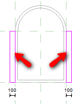
Define the extrusion height to -250mm.
Now we need to define the brick material. Click extrusion properties. In the opened dialog box, click the material field, and click the ‘…’ button next to it. You have to click the field first before you can see the button. It’s not the one in formula column!
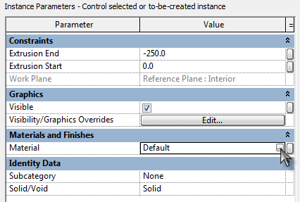
Now another dialog box is opened. Click duplicate button on the bottom left of this dialog. Give it name vertical brick.
Now we have a new material definition, let us change it. On the right side, click ‘…’ button in surface pattern group. We are going to create a new pattern for this material.

In the next dialog box, change the pattern type to model. Then click new button.
Change the pattern name and line spacing.
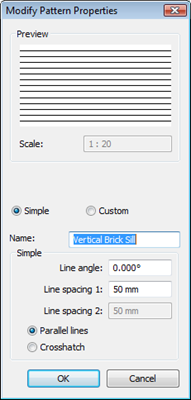
Click OK twice until we back to the material dialog box. Change the material shading to distinguish it with our wall. Optional: change the rendering material too, so you can also see brick pattern when you render your model.
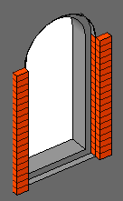
Click OK until all dialog closed. Click finish extrusion. Review your window.
Creating Tilt Soldier
Open left elevation view (or right, your choice). Draw a rectangle with size 250×50 (my assumption for the brick size, you may use your own size if you don’t feel it’s right). Rotate and move it as necessary. I use 5 deg for this profile.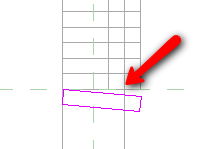
Open the extrusion properties. Click the parameter button next to extrusion end value. Select Width from opened dialog box. This means our soldier will use the same width as our window.

The last one is creating another material. Use this properties for the pattern.
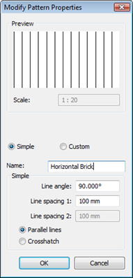
Close all dialogs, and click finish extrusion. Now if you see your extrusion like this, don’t panic!
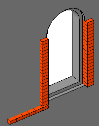
Select the extrusion, and click edit work plane in contextual tab on Revit ribbon.
In the opened dialog, select right reference plane, and click OK.
Creating Arc Soldier
The last one: arc brick soldier. This feature is also created using extrusion. I believe you will have no problem creating the extrusion. But our problem here is there is no pattern we can use to match this form orientation.There is no feature we can use to make the pattern automatically adjusted with the window size. At least there is no way I can find. Revit has limited geometry constraint to control such pattern. I would love to see Revit has geometry constraints in the future :)
So I would suggest you to leave it without pattern, and add the pattern later in your project elevation view. OR you can create separate families for each sizes. It’s your choice. I think the later is a better choice. At least you only to define it once, not repeatedly in your project.
We will talk about Revit detailing later.
If you decided to create model lines in this particular window size, then you can follow these steps. Remember, by using this method you can’t modify this window by changing the windows width later. You need to create a different family to have a different size.
Adding Model Lines
We can only use vertical or horizontal pattern. So what we can do is we can create a model line and array it. The alternative is creating a void to cut the arch to give the brick effect, but if you have dozens or even hundreds of Windows, you will not want to use it.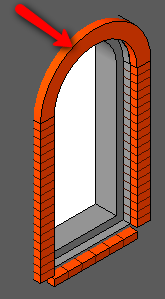
Open left elevation view. Create a reference plane right on the soldier face, exterior side.
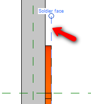
Select the work plane,change its name in element properties. Give it name soldier face.
Open exterior elevation view. Change the active work plane to soldier face.
Draw a model line, overlapped with the vertical brick (shown by the arrow below).
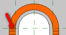
Select it, and click array

Change the array mode to radial, the array number to 25. And change move to: to last.
You will need to move the rotation center to be coincident with the arc. Click and drag the rotation center to move it.

Move your pointer to the right of the rotation center, until snap to X axis. Click your mouse to define the start angle. Rotate your pointer 180 deg clock wise. Click your mouse again.
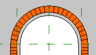
Try to change the window size.
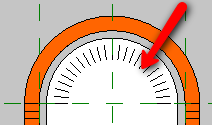
We can see the pattern is not adjusted. This is the problem I mentioned previously. This is why we can’t change the window size.
So if you want to create different sizes, save this one as a different family and add model lines in your new family.
Creating Keystone
I would leave this a challenge for you. This is not hard at all. I use two extrusion to create this form.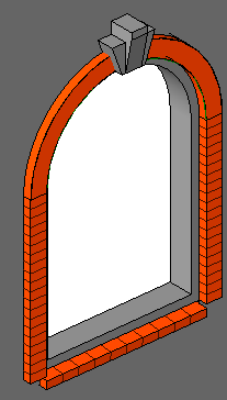
Can you create it? If you have difficulties, I can write about it. But after several tutorial, I want you to try it first.
Modifying Window Opening
The last thing we need to modify is the opening cut. We need to correct the opening cut after we added the brick soldiers. Edit the opening cut like below. You can see how to do it in the first step of this tutorial.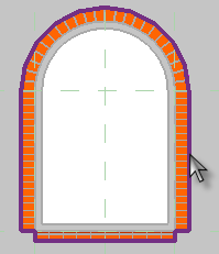
If you don’t modify the opening cut, then when we create a wall schedule, the opening will not be reported correctly. Your wall may be reported to have larger volume.
Source:cad-notes.com


Không có nhận xét nào:
Đăng nhận xét